
IGES Problems Eliminated
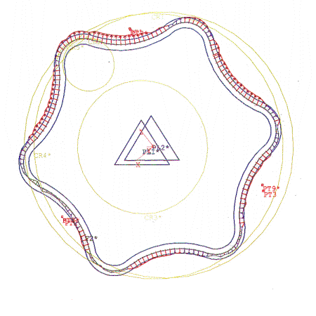
| The Part: | Small (25.0 mm diam) die insert. |
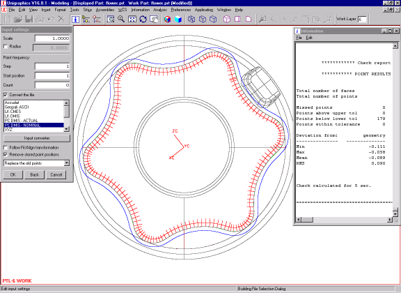
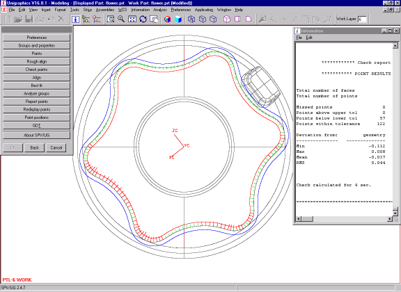
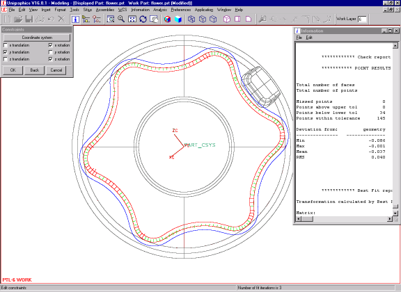
| The Task: | Inspect the profile of the part with 0.100 mm tolerance. This company used IGES file to inspect this part in PC-DMIS. The first picture represents comparison between the "nominal" points generated by PC-DMIS and the nominal CAD model. We used our own SPV to evaluate how far the "nominal" points are from the CAD surface inside Unigraphics®. The second image shows the results as reported by the third party software. Then we checked and best-fitted the actual center-of-probe points to the CAD model inside Unigraphics®. |
| The Results: | PC-DMIS reports the part being oversized despite the fact that it was recut number of times. In reality the part is undersized, with a mean of -0.037 mm after best fit and 34 (out of 179) points below the lower tolerance of -0.050 mm. The real reason is that the CMM software did not interpret the IGES file properly and all "nominal" hits where generated off the actual surface anywhere from -0.058 mm all the way down to -0.111 mm. On the other hand the NC cutter path was generated inside UG. Is IGES any good? Sometimes, but when there is a problem you wouldn't even know. |
| Highlights: | Eliminate loss of accuracy and reduce scarp by using integrated inspection. |
Sitius Inc., Copyright 1998-2015